
Installation guide
SITE PREPARATION
For optimal installation, ensure the surface grade does not exceed 1%. Undulations or steeper slopes will extend the process, requiring additional module adjustments.

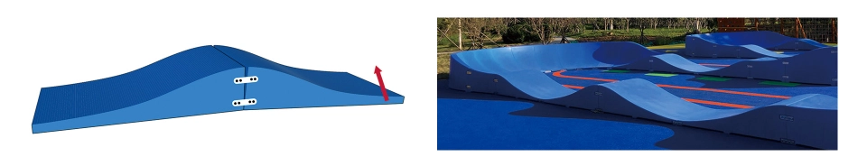
Note: to minimize gaps between sections, apply external force in this direction: lift or use a dolly to bend the modular piece upwards, then secure with a plate, bolt, and washer. This prevents large gaps during further installation.
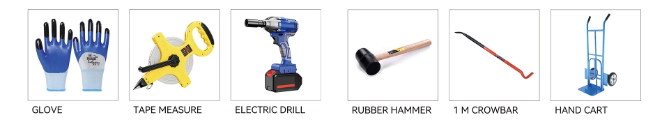
TOOL & EQUIPMENT LIST
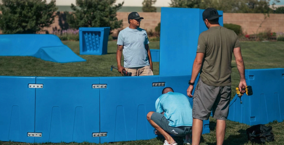
Two adults can lift a single module easily; use a hand cart or dolly for transport. Hand-thread bolts before using impact tools.
LAYOUT PROCEDURE
Example for “Velocity Loop 1” layout; apply similar methodology to others.
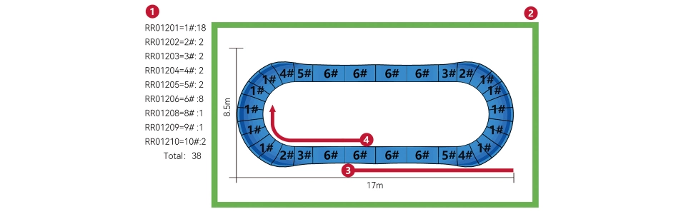
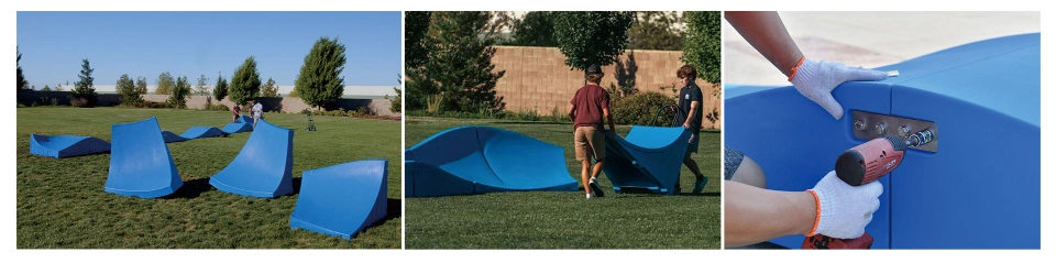
1.Count modules per box label and remove outer packaging.
2.As shown in the figure, position modules within the green frame line, allowing gaps between them.
3.Determine the reference edge as indicated by the red line.
4.Connect modules sequentially in a clockwise direction.